Theoretical Background: Robot Operating System 2
Module 1 Theory: ROS 2 Architecture and Concepts
1.5.1 What is ROS 2
ROS 2 (Robot Operating System 2) is not an operating system in the traditional sense. It is a middleware framework that provides the infrastructure for building robotic applications. ROS 2 supplies a standardized communication layer, hardware abstraction, device drivers, common algorithm implementations, package management, and development tools. It runs on top of a conventional operating system (Ubuntu Linux, macOS, or Windows) and allows developers to build complex robotic systems as collections of loosely coupled, interoperable software modules.
Key Clarification: The word “operating system” in the name is a historical artifact from ROS 1. ROS 2 provides operating-system-like services (inter-process communication, hardware abstraction, process management) to robotic applications, but it does not manage memory, schedule threads, or control hardware at the kernel level. It is more accurately described as a robotics middleware framework.
The fundamental design philosophy of ROS 2 is modularity. A robotic system is decomposed into independent processes called nodes, each responsible for a single well-defined task (reading a sensor, computing a plan, controlling a motor). Nodes communicate through well-defined interfaces, allowing them to be developed, tested, and replaced independently. This architecture enables code reuse across different robot platforms: a path planning node written for one robot works on any robot that publishes odometry and subscribes to velocity commands using the standard message types.
1.5.2 ROS 2 Architecture
DDS-Based Communication
The most significant architectural change from ROS 1 to ROS 2 is the adoption of the Data Distribution Service (DDS) as the underlying communication middleware. DDS is an OMG (Object Management Group) standard for real-time publish/subscribe communication, used extensively in defense, aerospace, and industrial systems. ROS 2 does not implement its own communication protocol; instead, it delegates all message transport to a DDS implementation through an abstraction layer called the ROS Middleware Interface (RMW).
This design means that ROS 2 inherits the properties of DDS: decentralized discovery (no single point of failure like the ROS 1 master), configurable Quality of Service (QoS) policies, support for real-time communication, and interoperability between different DDS vendors. Multiple DDS implementations are available (Fast DDS, Cyclone DDS, Connext DDS), and the RMW layer allows switching between them without modifying application code.
Nodes
A node is the fundamental unit of computation in ROS 2. Each node is a process (or a thread within a process) that performs a specific function. A typical mobile robot system might include nodes for motor control, odometry computation, LiDAR processing, SLAM, path planning, and velocity command generation. Nodes are identified by unique names within a namespace hierarchy that prevents naming conflicts in multi-robot systems.
Executors
Executors manage the scheduling and execution of callbacks within a node. When a message
arrives on a subscribed topic or a service request is received, the corresponding callback
function is placed in a queue. The executor processes this queue according to its scheduling
policy. The SingleThreadedExecutor processes callbacks sequentially; the
MultiThreadedExecutor allows concurrent callback execution using a thread pool. Custom
executors can implement priority-based scheduling for real-time applications.
Lifecycle Nodes (Managed Nodes)
Standard ROS 2 nodes begin executing immediately upon creation. Lifecycle nodes add a state
machine with well-defined states: Unconfigured, Inactive, Active, and Finalized. Transitions
between states (configure, activate, deactivate, cleanup,
shutdown) are triggered explicitly, allowing the system to bring up nodes in a
controlled sequence. This is critical for robotic systems where hardware initialization must
complete before software begins publishing data. A LiDAR driver node, for example, should not
publish scan data until the sensor hardware has been configured and validated.
1.5.3 Communication Paradigms
ROS 2 provides four distinct communication patterns, each suited to different interaction requirements.
Topics: Publish/Subscribe
Topics implement asynchronous, many-to-many communication. A publisher sends messages to a named topic; any number of subscribers receive those messages. Publishers and subscribers are decoupled — neither knows how many (if any) counterparts exist. This pattern is ideal for continuous data streams: sensor readings, state estimates, and command signals.
- Directionality: Unidirectional (publisher to subscriber)
- Cardinality: Many publishers, many subscribers per topic
- Timing: Asynchronous — publisher sends at its own rate, subscribers receive when data is available
- Typical Use: Sensor data (
/scan,/image_raw), state estimates (/odom), velocity commands (/cmd_vel)
Key Property: Topic communication is best-effort by default. If a subscriber is slower than the publisher, messages may be dropped. QoS policies (discussed below) allow configuring reliability, durability, and history depth to control this behavior.
Services: Request/Response
Services implement synchronous, one-to-one communication. A client sends a request to a named service and blocks until the server returns a response. This pattern is suited for discrete, short-duration operations: querying a parameter, triggering a computation, or commanding a state change.
- Directionality: Bidirectional (request from client, response from server)
- Cardinality: Many clients, one server per service
- Timing: Synchronous — client blocks until response arrives
- Typical Use: Querying map data, resetting odometry, enabling/disabling a subsystem
Limitation: Services are blocking and should not be used for long-running operations. A service call that takes several seconds would stall the calling node’s executor, preventing it from processing other callbacks.
Actions: Goal/Feedback/Result
Actions implement asynchronous, long-running task execution with progress feedback. A client sends a goal to an action server, receives periodic feedback during execution, and obtains a final result upon completion. Goals can be canceled mid-execution. This pattern is built on top of topics and services internally.
- Directionality: Bidirectional with streaming feedback
- Cardinality: Many clients, one server per action
- Timing: Asynchronous — client does not block; feedback arrives as a stream
- Typical Use: Navigation to a goal pose (Nav2), following a trajectory, executing a manipulation sequence
Key Property: Actions are the appropriate pattern for any task that takes more than a few seconds and where the client needs progress updates or the ability to cancel.
Parameters
Parameters provide runtime configuration for nodes. Each node maintains a set of named parameters (key-value pairs) that can be read and modified at runtime through a standardized interface. Parameters are typed (boolean, integer, double, string, arrays) and can trigger callback functions when modified.
- Typical Use: PID gains, sensor polling rates, topic remapping, threshold values
- Setting Parameters: Through launch files, command-line arguments, YAML configuration files, or programmatic parameter client calls
1.5.4 Key Message Types for Mobile Robotics
ROS 2 defines standardized message types that ensure interoperability across different robot platforms and algorithm implementations. Four message types are particularly central to mobile robot systems.
geometry_msgs/Twist for Velocity Commands
The Twist message encodes linear and angular velocity in three dimensions. For a
planar mobile robot, only two fields are used: linear.x (forward velocity in
m/s) and angular.z (rotational velocity in rad/s). This message is published
on the /cmd_vel topic by planning and teleoperation nodes, and consumed by the motor
controller node.
# Twist message structure
        geometry_msgs/msg/Twist
        geometry_msgs/msg/Vector3 linear
        float64 x    # forward velocity (m/s)
        float64 y    # lateral velocity (m/s, zero for differential drive)
        float64 z    # vertical velocity (m/s, zero for ground robots)
        geometry_msgs/msg/Vector3 angular
        float64 x    # roll rate (rad/s, zero for ground robots)
        float64 y    # pitch rate (rad/s, zero for ground robots)
        float64 z    # yaw rate (rad/s)
nav_msgs/Odometry for Robot State
The Odometry message encodes the robot’s estimated position, orientation, and velocity
in a reference frame. It is published on the /odom topic by the odometry computation
node. The pose includes position (, , ) and orientation as a quaternion, along with a
covariance matrix that quantifies the uncertainty in the estimate.
sensor_msgs/LaserScan for LiDAR
The LaserScan message encodes a single sweep of a planar LiDAR sensor. It contains
the angular range (angle_min to angle_max), angular increment between rays,
range measurements as a float array, and intensity values. Published on the /scan
topic, this message is consumed by SLAM and obstacle detection nodes. The ranges array
typically contains 360–1440 measurements per sweep, depending on the sensor resolution.
tf2 for Coordinate Transformations
The tf2 library maintains a tree of coordinate frame transformations that describes the spatial
relationship between every frame in the system. The map frame is the global reference.
The odom frame drifts relative to map but is continuous (no jumps). The
base_link frame is attached to the robot body. Sensor frames (laser_frame,
camera_frame) are fixed relative to base_link.
# Standard frame hierarchy for a mobile robot
        map -> odom -> base_link -> laser_frame
        -> camera_frame
        -> imu_frame
Nodes publish static transforms (sensor mounting positions) and dynamic transforms
(odom to base_link from odometry, map to odom from
localization). Any node can query tf2 to obtain the transform between any two frames at any
point in time, enabling sensor data from different frames to be combined in a common reference.
1.5.5 ROS 2 vs. ROS 1
ROS 1, first released in 2007, became the de facto standard for robotics research. However, its architecture had fundamental limitations that prevented adoption in commercial and safety-critical applications. ROS 2 was redesigned from the ground up to address these limitations.
- Centralized Master vs. Decentralized Discovery: ROS 1 required a running
roscoremaster node for all communication. If the master crashed, the entire system failed. ROS 2 uses DDS peer-to-peer discovery with no central point of failure. - Real-Time Support: ROS 1 had no real-time guarantees. ROS 2’s executor architecture and DDS QoS policies enable deterministic callback scheduling when combined with a real-time operating system kernel.
- Security: ROS 1 had no built-in security — any process on the network could publish or subscribe to any topic. ROS 2 integrates DDS Security for authentication, encryption, and access control.
- Multi-Platform: ROS 1 officially supported only Ubuntu Linux. ROS 2 supports Ubuntu, macOS, and Windows.
- Quality of Service (QoS): ROS 1 used TCP for reliable communication and UDP for best-effort, with no fine-grained control. ROS 2 exposes DDS QoS profiles that configure reliability (reliable vs. best-effort), durability (volatile vs. transient-local), history depth, and deadline enforcement.
- Multi-Robot Support: ROS 1 required complex workarounds (namespacing, separate masters) for multi-robot systems. ROS 2 uses DDS domains and namespaces natively, allowing multiple robots to share a network with isolated communication.
1.5.6 ROS 2 Ecosystem
The ROS 2 ecosystem includes a rich set of tools and libraries that accelerate robot development.
Gazebo is a physics-based simulation environment that models robots, sensors, and
environments. Gazebo simulates sensor outputs (LiDAR scans, camera images, IMU data) and
physics interactions (collisions, gravity, friction), allowing complete robot software stacks to
be developed and tested without hardware. The ros_gz_bridge package translates
between Gazebo and ROS 2 topics.
RViz2 is a 3D visualization tool for displaying robot state, sensor data, maps, paths, and coordinate frames in real time. It subscribes to standard ROS 2 topics and renders the data graphically. RViz2 is essential for debugging perception, localization, and planning algorithms.
Nav2 (Navigation 2) is the standard navigation stack for ROS 2 mobile robots. It provides global path planning, local trajectory optimization, recovery behaviors, and waypoint following. Nav2 implements the behavior tree paradigm for composing complex navigation behaviors from simple building blocks.
SLAM Toolbox provides online and offline 2D SLAM capabilities, producing occupancy grid maps from LiDAR data while simultaneously estimating the robot’s pose. It is the recommended SLAM solution for ROS 2 mobile robots operating in indoor environments.
rosbridge provides a WebSocket interface to ROS 2, allowing web browsers and non-ROS applications to publish and subscribe to topics, call services, and interact with the ROS 2 system through JSON messages. This enables web-based dashboards, remote monitoring interfaces, and cross-platform control applications.
1.5.7 Development Workflow
Workspace Structure
ROS 2 code is organized into workspaces, each containing a src directory with one or
more packages. The standard workspace layout is:
# ROS 2 workspace structure
        ros2_ws/
        src/
        my_robot_pkg/
        package.xml          # package metadata and dependencies
        CMakeLists.txt       # build instructions (C++) or setup.py (Python)
        my_robot_pkg/        # Python module directory
        __init__.py
        publisher_node.py
        launch/
        robot_launch.py    # launch file for starting multiple nodes
        config/
        params.yaml        # parameter configuration file
Packages
A package is the smallest unit of distributable software in ROS 2. Each package declares its
dependencies in package.xml and its build instructions in CMakeLists.txt
(for C++ ament_cmake packages) or setup.py/setup.cfg (for Python
ament_python packages). Packages encapsulate nodes, message definitions, launch
files, and configuration files.
Build System
ROS 2 uses colcon as its build tool. The colcon build command compiles all
packages in the workspace, resolving dependencies automatically. After building, the workspace
overlay must be sourced (source install/setup.bash) to make the built packages
available to the current shell session.
Launch Files
Launch files orchestrate the startup of multiple nodes with configured parameters, topic remappings, and namespaces. ROS 2 uses Python-based launch files that provide programmatic control over the launch process. A single launch file can start all nodes for a complete robot system, set parameters from YAML files, and define conditional logic based on launch arguments.
# Minimal Python launch file structure
        from launch import LaunchDescription
        from launch_ros.actions import Node

        def generate_launch_description():
        return LaunchDescription([
        Node(
        package='my_robot_pkg',
        executable='publisher_node',
        name='cmd_vel_publisher',
        parameters=[{'linear_speed': 0.5}],
        remappings=[('/cmd_vel', '/robot1/cmd_vel')]
        ),
        ])
Minimal Publisher Node
A ROS 2 node is implemented as a class that inherits from rclpy.node.Node (Python) or
rclcpp::Node (C++). The following shows the structure of a minimal publisher node:
# Minimal publisher node (Python)
        import rclpy
        from rclpy.node import Node
        from geometry_msgs.msg import Twist

        class VelocityPublisher(Node):
        def __init__(self):
        super().__init__('velocity_publisher')
        self.publisher = self.create_publisher(Twist, '/cmd_vel', 10)
        self.timer = self.create_timer(0.1, self.publish_velocity)  # 10 Hz

        def publish_velocity(self):
        msg = Twist()
        msg.linear.x = 0.5   # 0.5 m/s forward
        msg.angular.z = 0.0  # no rotation
        self.publisher.publish(msg)

        def main():
        rclpy.init()
        node = VelocityPublisher()
        rclpy.spin(node)          # process callbacks until shutdown
        node.destroy_node()
        rclpy.shutdown()
The create_publisher call registers the node as a publisher on the
/cmd_vel topic with a queue depth of 10. The create_timer call schedules
the publish_velocity callback at 10 Hz. The rclpy.spin call enters the
executor loop, processing timer and subscription callbacks until the node is shut down.
Integration: Theory to Practice
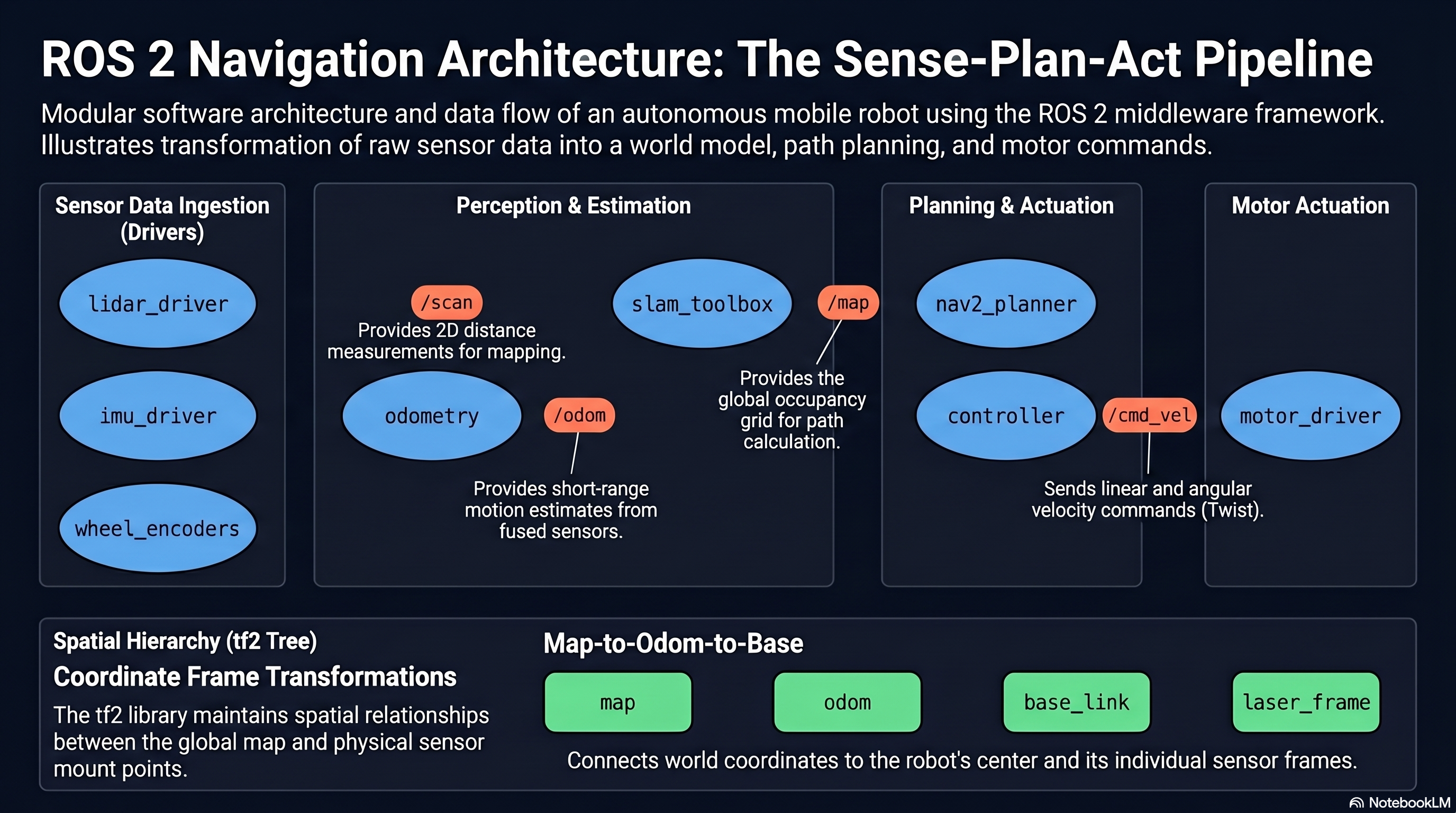
The architectural concepts presented here directly determine how a mobile robot software system
is structured. The decomposition into nodes maps to the sense-plan-act pipeline: a LiDAR driver
node (sense) publishes /scan, a SLAM node (perceive) subscribes to /scan and
publishes the map and localization transforms on tf2, a Nav2 planner node (plan) subscribes to
the map and goal pose to publish a path, and a controller node (act) subscribes to the path and
publishes /cmd_vel. The choice of communication paradigm matters: sensor data flows
over topics (continuous, asynchronous), navigation goals use actions (long-running with feedback
and cancellation), and configuration changes use parameters or services (discrete, synchronous).
QoS profiles must be matched between publishers and subscribers — a LiDAR driver publishing
with best-effort reliability will not deliver data to a subscriber expecting reliable delivery.
The tf2 frame hierarchy ensures that sensor data from different physical locations on the robot
can be correctly fused in a common coordinate frame.
Theoretical Design Choices
Why DDS as the communication middleware: DDS was selected because it provides decentralized discovery, configurable QoS, real-time communication support, and security — all properties that ROS 1 lacked and that are required for commercial robotics deployment. Rather than implementing these features from scratch, the ROS 2 designers leveraged decades of DDS development in defense and industrial systems. The RMW abstraction layer ensures that ROS 2 is not locked to a single DDS vendor, allowing users to choose the implementation that best fits their latency, throughput, and licensing requirements.
Why lifecycle nodes matter for robotic systems: Robotic systems have complex startup dependencies: sensors must be initialized before perception algorithms run, and perception must produce valid data before planners activate. Without lifecycle management, race conditions arise where a planner requests a map from a SLAM node that has not yet received its first LiDAR scan. Lifecycle nodes make these dependencies explicit and enforceable, turning a fragile startup sequence into a deterministic state machine.
Why QoS profiles are essential for reliable operation: A mobile robot operating in a real environment cannot afford to lose critical messages. A velocity command that is dropped may cause the robot to continue moving when it should stop. Conversely, buffering every historical LiDAR scan wastes memory and introduces latency. QoS profiles allow each communication channel to be configured for its specific requirements: reliable delivery for velocity commands, best-effort for high-frequency sensor data, transient-local durability for map data that late-joining subscribers need to receive. Mismatched QoS between publisher and subscriber is a common source of “silent failure” in ROS 2 systems, where nodes appear to be running but no data flows between them.